了解Activiti bpmn图表对应的XML文件
发布时间:『 2016-04-07 09:19』 博客类别:activiti
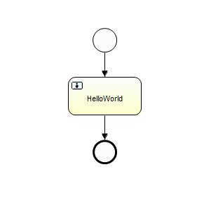
前面我们绘制了一个简单的流程图表,这个图表的本质,其实就是一个xml文件。我们大体熟悉下结构,不需要做太深入的研究;
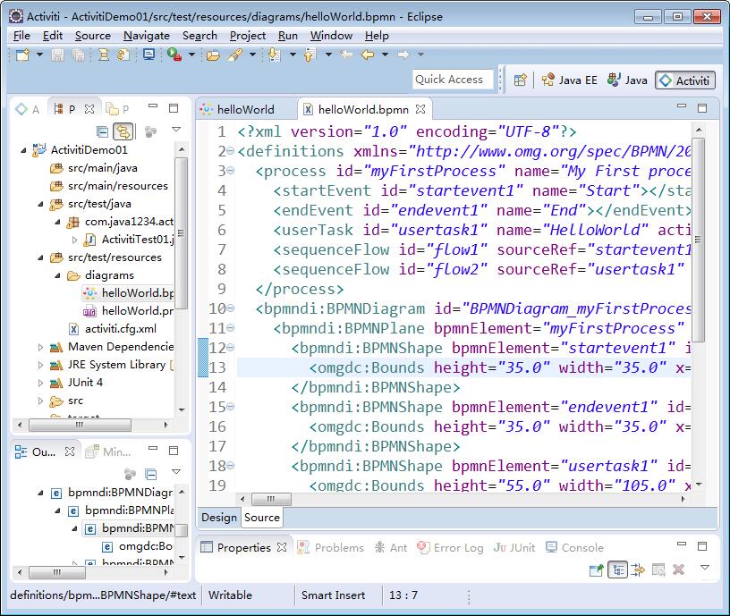
我们右击helloWorld.bpmn文件,open with -> XML Editor ;

XML如下:
<?xml version="1.0" encoding="UTF-8"?>
<definitions xmlns="http://www.omg.org/spec/BPMN/20100524/MODEL"
              xmlns:xsi="http://www.w3.org/2001/XMLSchema-instance"
              xmlns:xsd="http://www.w3.org/2001/XMLSchema"
              xmlns:activiti="http://activiti.org/bpmn"
              xmlns:bpmndi="http://www.omg.org/spec/BPMN/20100524/DI"
              xmlns:omgdc="http://www.omg.org/spec/DD/20100524/DC"
              xmlns:omgdi="http://www.omg.org/spec/DD/20100524/DI"
              typeLanguage="http://www.w3.org/2001/XMLSchema"
              expressionLanguage="http://www.w3.org/1999/XPath"
              targetNamespace="http://www.activiti.org/test">
  <process id="myFirstProcess" name="My First process" isExecutable="true">
    <startEvent id="startevent1" name="Start"></startEvent>
    <endEvent id="endevent1" name="End"></endEvent>
    <userTask id="usertask1" name="HelloWorld" activiti:assignee="java1234_小锋"></userTask>
    <sequenceFlow id="flow1" sourceRef="startevent1" targetRef="usertask1"></sequenceFlow>
    <sequenceFlow id="flow2" sourceRef="usertask1" targetRef="endevent1"></sequenceFlow>
  </process>
  <bpmndi:BPMNDiagram id="BPMNDiagram_myFirstProcess">
    <bpmndi:BPMNPlane bpmnElement="myFirstProcess" id="BPMNPlane_myFirstProcess">
      <bpmndi:BPMNShape bpmnElement="startevent1" id="BPMNShape_startevent1">
        <omgdc:Bounds height="35.0" width="35.0" x="200.0" y="40.0"></omgdc:Bounds>
      </bpmndi:BPMNShape>
      <bpmndi:BPMNShape bpmnElement="endevent1" id="BPMNShape_endevent1">
        <omgdc:Bounds height="35.0" width="35.0" x="200.0" y="200.0"></omgdc:Bounds>
      </bpmndi:BPMNShape>
      <bpmndi:BPMNShape bpmnElement="usertask1" id="BPMNShape_usertask1">
        <omgdc:Bounds height="55.0" width="105.0" x="165.0" y="110.0"></omgdc:Bounds>
      </bpmndi:BPMNShape>
      <bpmndi:BPMNEdge bpmnElement="flow1" id="BPMNEdge_flow1">
        <omgdi:waypoint x="217.0" y="75.0"></omgdi:waypoint>
        <omgdi:waypoint x="217.0" y="110.0"></omgdi:waypoint>
      </bpmndi:BPMNEdge>
      <bpmndi:BPMNEdge bpmnElement="flow2" id="BPMNEdge_flow2">
        <omgdi:waypoint x="217.0" y="165.0"></omgdi:waypoint>
        <omgdi:waypoint x="217.0" y="200.0"></omgdi:waypoint>
      </bpmndi:BPMNEdge>
    </bpmndi:BPMNPlane>
  </bpmndi:BPMNDiagram>
</definitions>
这里definitions是一个总的节点;下面process是流程节点,bpmndi:BPMNDiagram是流程图表定义节点;
bpmndi:BPMNDiagram这个节点里面就不用看了。是定义图标的位置,结构的。
我们重点看下process节点:

这里我们看到的有三个节点,开始节点,结束节点,用户任务节点。这里还有两根连线,开始节点- > 用户任务节点 连线;
用户任务节点 -> 结束节点 连线;
对应到xml 是5个dom节点;
<startEvent id="startevent1" name="Start"></startEvent>
<endEvent id="endevent1" name="End"></endEvent>
<userTask id="usertask1" name="HelloWorld" activiti:assignee="java1234_小锋"></userTask>
<sequenceFlow id="flow1" sourceRef="startevent1" targetRef="usertask1"></sequenceFlow>
<sequenceFlow id="flow2" sourceRef="usertask1" targetRef="endevent1"></sequenceFlow>
这里startEvent对应开始节点; endEvent对应结束节点;
userTask对应用户任务节点; sequenceFlow对应用户任务节点,sourceRef targetRef 属性对应从哪里连接到哪里去。
还有其他的简单属性,大家也能猜得出来意思。当然以后流程越复杂,生成的对应XML文件也越复杂,节点多,属性也多。
这个帖子只是让大家有个大体的熟悉,不需要深入研究;
关键字:
Activiti


Java1234_小锋
(知识改变命运,技术改变世界)
- Java核心基础(145)
- Mysql(2)
- Docker(35)
- Dubbo(7)
- 007项目(0)
- SVN(22)
- QQ第三方登录(6)
- mybatis-plus(20)
- Mycat(30)
- Layui(2)
- 微信扫码登录(4)
- Git(50)
- SpringCloud(33)
- Tomcat(6)
- 支付宝接口(3)
- NodeJs(1)
- IDEA(24)
- SpringBoot(11)
- Nginx(24)
- Vue.js(50)
- jsoup(6)
- shiro(1)
- hibernate(1)
- EhCache缓存框架(4)
- webservice(10)
- CAS单点登录(7)
- elasticsearch(31)
- Redis(17)
- maven(6)
- 活动(20)
- centos(25)
- log4j日志(8)
- IT之路(26)
- activiti(26)
- 随心生活(19)
- java爬虫技术(14)
- 网站SEO(2)
- httpclient(7)
- htmlunit(10)
- 2026年01月(1)
- 2021年10月(1)
- 2021年02月(3)
- 2020年11月(3)
- 2020年10月(4)
- 2020年09月(7)
- 2020年08月(18)
- 2020年07月(21)
- 2020年06月(37)
- 2020年05月(17)
- 2020年04月(12)
- 2020年03月(10)
- 2020年02月(14)
- 2020年01月(12)
- 2019年12月(15)
- 2019年11月(27)
- 2019年10月(5)
- 2019年09月(1)
- 2019年08月(4)
- 2019年07月(28)
- 2019年06月(16)
- 2019年05月(4)
- 2019年04月(3)
- 2019年03月(2)
- 2019年02月(7)
- 2019年01月(20)
- 2018年12月(2)
- 2018年11月(5)
- 2018年10月(30)
- 2018年09月(11)
- 2018年08月(5)
- 2018年07月(9)
- 2018年06月(4)
- 2018年05月(4)
- 2018年04月(3)
- 2018年03月(7)
- 2018年02月(6)
- 2018年01月(13)
- 2017年12月(3)
- 2017年11月(10)
- 2017年10月(1)
- 2017年09月(9)
- 2017年08月(12)
- 2017年07月(19)
- 2017年06月(21)
- 2017年05月(1)
- 2017年04月(12)
- 2017年03月(13)
- 2017年02月(12)
- 2017年01月(14)
- 2016年12月(8)
- 2016年11月(25)
- 2016年10月(16)
- 2016年09月(13)
- 2016年08月(20)
- 2016年07月(12)
- 2016年06月(36)
- 2016年05月(10)
- 2016年04月(19)
- 2016年03月(14)
- 2016年02月(23)
- 2016年01月(1)
Powered by Java1234 V3.0
Copyright © 2012-2016 Java知识分享网 版权所有